Trevor Gale's 'Constructed' Page.
Item(s) constructed...
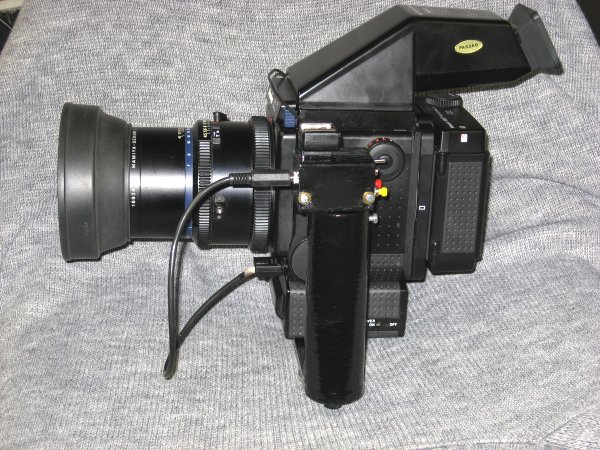
Now I have moved up a grade in my 6 x 7 film-format kit (from two RB67 kits to two RZ-67 pro II kits) I find that the small accessories such as mount brackets, for example, are a tad on the pricey side! So without much further ado, I decided to make two of these mounts myself, and this is just an example of what can be made in around 4 hours using basic aluminium stock and a bit of brass stock using the saw and the lathe. The bracket mount on its own can be seen below:-
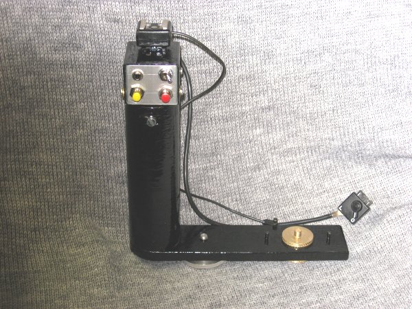
... together with another (annotated) view below:-
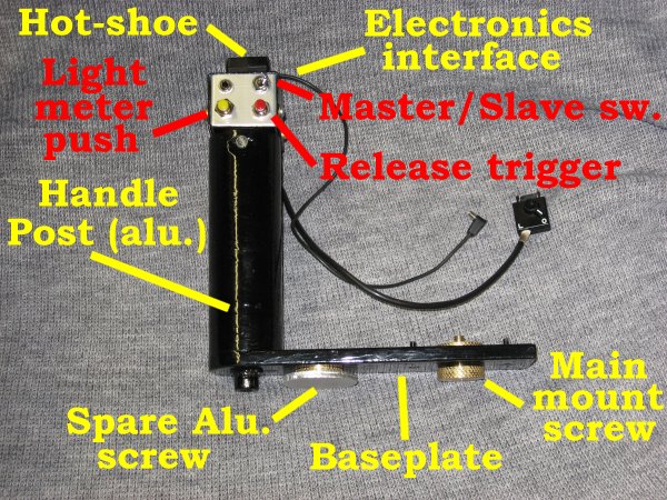
The baseplate is made from a cut of 6mm aluminium, 40mm wide and curved at one end to match up to the handle piece. The handle piece was turned from round aluminium stock in the lathe, drilled and tapped at the bottom to allow fixing to the baseplate using an M8 Allen-head screw, and the top was centre drilled 6mm to allow the insertion of either a hot-shoe on its own or, as is shown, an electrical interface with separate light-metering and shutter-release buttons and incorporating a master / slave select switch which allows the use of a remote shutter control when all is tripod-mounted, etc. Finger indentations on this grip were firstly roughly milled and then filed out.
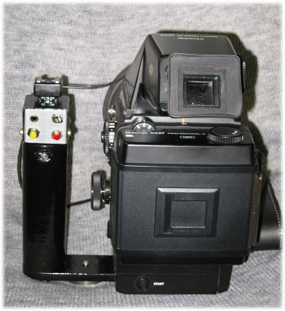
Additional to the grip since this first type is a lined leather carry support strap: this was made from an old unused leather belt, with the ends provided with securing rings at the bottom, held by the M8 bolt, and at the top, where the accessory box can fit through the ring before tightening, as can be seen in:
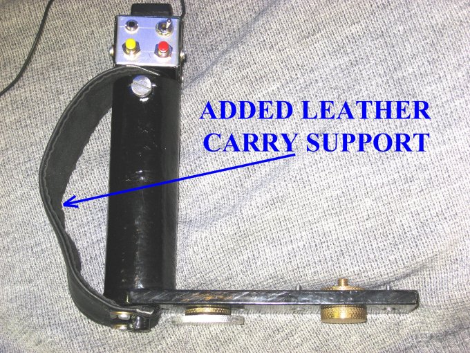 .
.
The baseplate is drilled oversize 6.2mm to allow the main fixing screw (the
brass one in the pictures) and also for the two 4mm locating-lugs which the
cameras receive. An extra 1/4-inch Whitworth thread was added to retain an
alternative aluminium screw which is used for lighter options.
Finally, the screwing itself was also turned from stock: both the main brass
retention screw and the take-up disc, both 1/4-inch British Whitworth which is
a standard camera fixing thread.
All was finished in black Hammerite paint for protection.
The elctronics is extremely simple and consists of a few diodes, two pushbuttons and a dual-pole dual-changeover switch and of course the entry and exit sockets for the connection to the camera body and with any remote device.
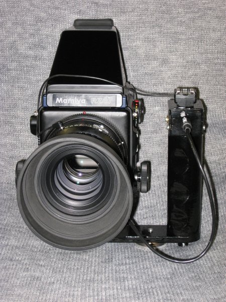
The mount as used on the cameras can be seen below:-
An extra box of simple electronics was designed and can be seen in the image:
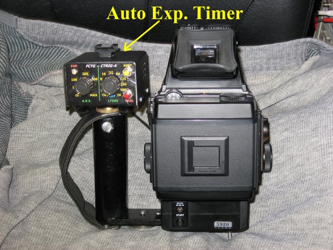
this box is designed to drive a pre-flash
anti-red-eye as well as provide for extra-long timed exposures (e.g. for the
night sky) [c] F.C.T.G. September 2008. Two main control areas provide for the
adjustment to suit the model in terms of anti-red-eye (it can be used with a studio
flash unit) in milliseconds, and the second control provides for long exposured
up to 1024S (2/4/8/16/32/64/125/250/500 and 1000 seconds nominal) and when used
in conjunction with the pre-delay in milliseconds, the anti-red-eye circuitry
provides start-of-exposure vibration avoidance.
Thank you for viewing, all images (c) F.C. Trevor Gale, July 14 - September 10, 2008.
 You can E-mail the
author of these pages (Trevor Gale) by using
this link, or by sending mail to tgale@trevang.com on the Dutch Internet
service provider XS4ALL.
You can E-mail the
author of these pages (Trevor Gale) by using
this link, or by sending mail to tgale@trevang.com on the Dutch Internet
service provider XS4ALL. 